Electronic components to make this simple LED circuit.
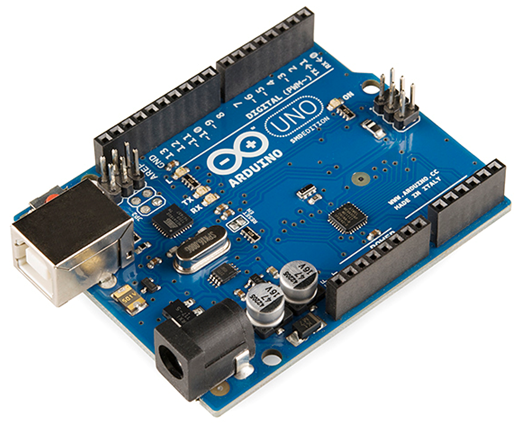
Arduino UNO
The Arduino Uno is a popular microcontroller board that is widely used for various electronics and DIY projects. It’s part of the Arduino platform, which provides an open-source and user-friendly way to create interactive electronic devices. Here are some key features and information about the Arduino Uno. Laern about basics of Arduino Uno here.
Microcontroller
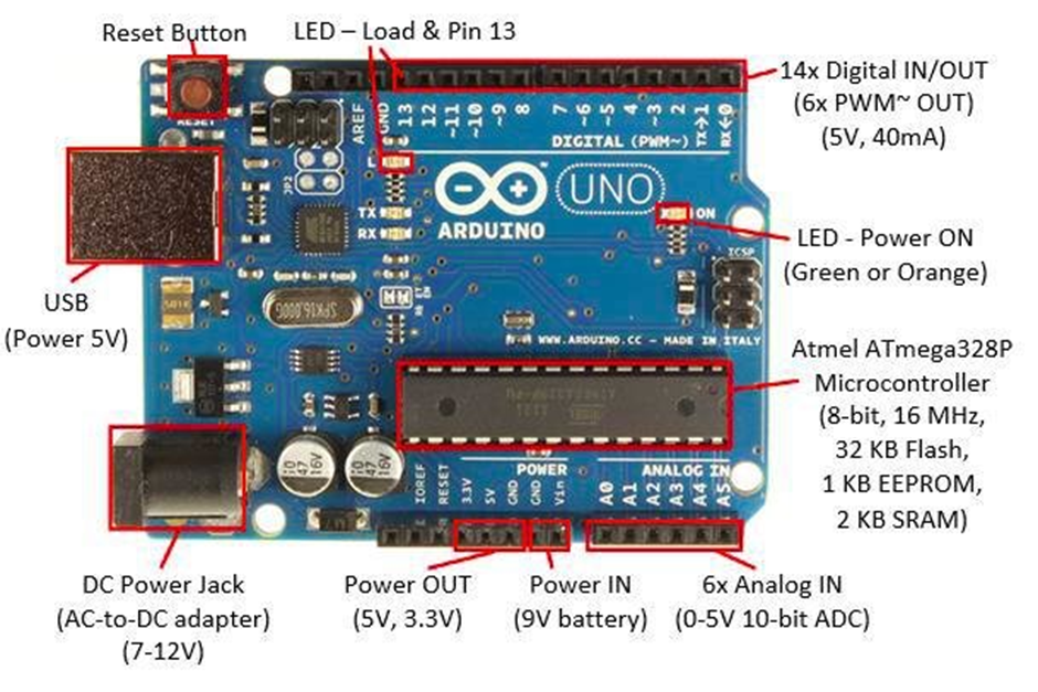
The heart of the Arduino Uno is the Atmega328P microcontroller, which has 32KB of flash memory for storing your program, 2KB of RAM for data storage, and various input/output pins for connecting to external components.
Digital and Analog Pins
The Arduino Uno has a total of 14 digital input/output pins (labeled D0 to D13) and 6 analog input pins (labeled A0 to A5). These pins can be used to read digital and analog signals and control various electronic components.
Voltage requirements
The Arduino Uno is typically powered by a 5V supply, and it can accept a range of input voltages from 7V to 12V through its barrel jack or directly from a USB connection.
USB Connection
It has a built-in USB interface, making it easy to connect to a computer for programming and serial communication.

Scientific diagram of an Arduino UNO Board
Materials Required to Make the Project
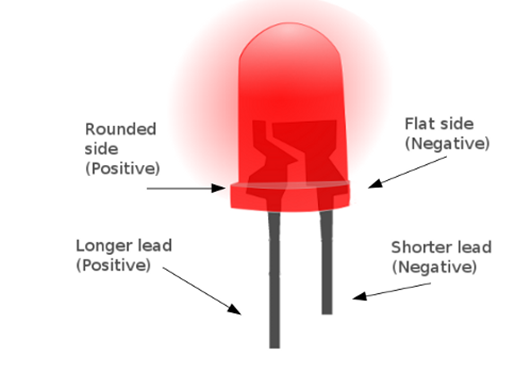
Light-Emitting Diodes (Blink an LED)
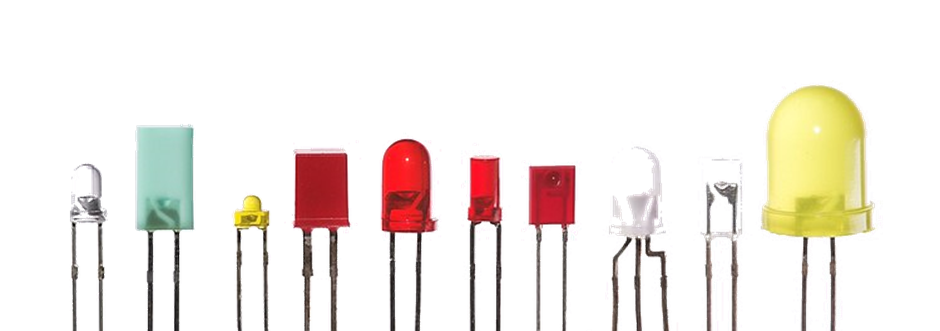
- To Blink an LED, or Light-Emitting Diode, use any color you want. It is a semiconductor device that emits light when an electric current passes through it.
- LEDs have two leads or legs: the longer one is the anode, which is the positive side, and the shorter one is the cathode, the negative side.
- It’s crucial to connect the LED in the correct polarity to make it emit light. If you reverse the polarity, the LED won’t light up.
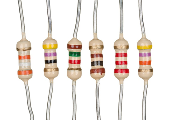
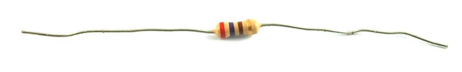
Resistors
- Resistors are passive electronic components that resist the flow of electric current. They are used to limit or control the current in a circuit.
- In the context of an LED circuit, a resistor is often added in series with the LED to limit the current passing through the LED. This helps protect the LED from too much current, which can damage it.
- The value of a resistor is measured in ohms (Ω), and the resistor’s resistance value determines how much it restricts the current. A higher resistance value results in less current flowing through the circuit.
- You can calculate the required resistance for an LED circuit using Ohm’s Law: R = (V_source – V_LED) / I, where R is the resistance, V_source is the source voltage (usually 5V for an Arduino), V_LED is the LED’s forward voltage, and I is the desired current.
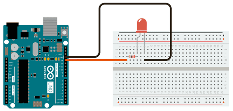
Breadboard
A breadboard is a fundamental tool used in electronics for building and prototyping electrical circuits without the need for soldering. It allows you to connect electronic components quickly and easily, such as resistors, LEDs, integrated circuits, and wires, to create and test circuits.
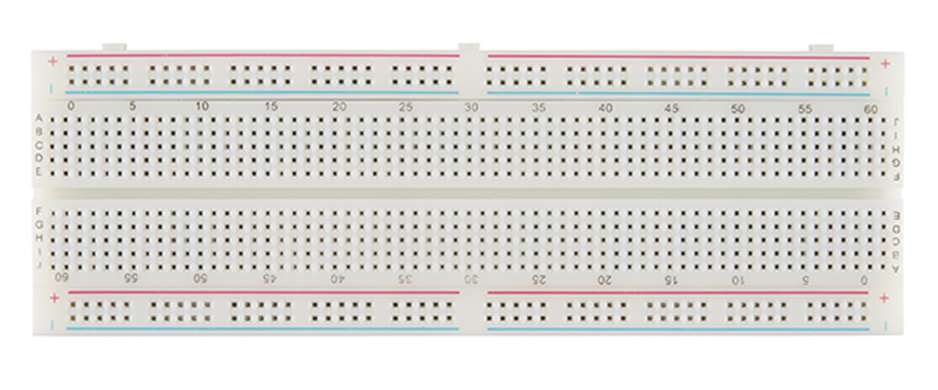
Breadboards typically consist of a plastic base with a grid of holes that are interconnected by metal clips or strips beneath the surface. The holes in the breadboard are organized into rows and columns, which provide a convenient way to connect components. The holes in the breadboard are used to insert the leads of electronic components.
- The holes in each row are electrically connected horizontally, allowing you to easily connect components in series.
- The columns of holes are not electrically connected to each other, which allows you to connect components in parallel.
Breadboards typically have power rails along the edges. There are usually two power rails: one for connecting to the positive voltage (usually labeled as +) and another for connecting to ground (usually labeled as -).
These power rails provide a convenient way to distribute power to various parts of your circuit.
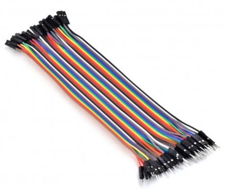
To build a circuit on a breadboard, you insert the component leads into the appropriate holes to create electrical connections. Use jumper wires to connect components across rows or columns as needed.
Ensure that components are correctly oriented and placed in the proper rows/columns.
Jumper Wires
Voltage (V), Current (A), and Resistance (Ω)
- Voltage (V): Voltage is the electrical potential difference between two points in a circuit. It’s measured in volts (V) and represents the “pressure” that drives current through a circuit. In the LED circuit, the source voltage is typically 5V from the Arduino.
- Current (A): Current is the flow of electric charge in a circuit. It’s measured in amperes (A) or milliamperes (mA). In the LED circuit, the resistor is used to limit the current to a safe value, usually around 10-20 mA for typical LEDs.
- Resistance (Ω): Resistance is the property of a component that opposes the flow of current. It’s measured in ohms (Ω). In the LED circuit, resistors are used to control the current by providing the necessary resistance.
What is Wiring Diagram?
A wiring diagram is a visual representation of how electrical components are connected in an electrical or electronic circuit. It’s a useful tool for understanding and planning the connections between various components, such as LEDs, resistors, and other electronic parts. You can make below diagram using pen and paper.
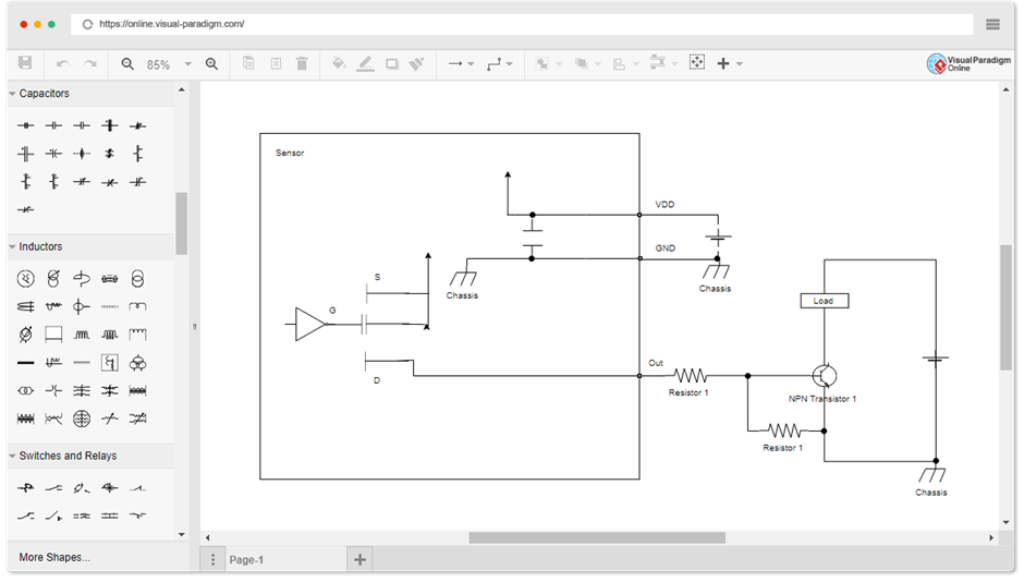
Or you can use any software such as Visual Paradigm Online.
Here’s how you can create a simple wiring diagram for the blinking LED project using an Arduino Uno.
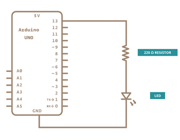
Wiring Diagram for Blinking LED Project
Blink an LED – Learn to connect wiring
Draw Arduino UNO
Draw a rectangle representing the Arduino Uno board. Label the pins you’re using.
For this project, you’ll need to label:
Digital Pin 13 (D13): This is where you’ll connect the anode (+) of the LED.
GND (Ground): This is where you’ll connect the cathode (-) of the LED.
Draw LED(s)
Draw a symbol for the LED. It typically looks like a small arrow pointing away from the anode (+) side.
Label the LED with “LED” and indicate the longer leg (anode) and shorter leg (cathode).
Connect the anode of the LED to Digital Pin 13 on the Arduino (D13).
Connect the cathode of the LED to a resistor.
Draw Resistor
Draw a resistor symbol (a zigzag line).
Label the resistor with its resistance value (e.g., 220-330Ω).
Connect one end of the resistor to the cathode of the LED.
Connect the other end of the resistor to the GND (Ground) on the Arduino.
Draw Power Supply
Label the source voltage of the Arduino (typically 5V).
Draw Wires
Draw lines to represent the wires that connect the components.
Label the wires to indicate their purpose, such as “LED to D13,” “Resistor to GND,” and so on.
Your wiring diagram should illustrate how all these components are connected in the circuit. It serves as a visual guide for assembling your circuit, making sure you connect everything correctly to create the blinking LED project.
Note
Remember to follow the wiring diagram carefully when you’re actually building the circuit to avoid any mistakes, and ensure that the LED is connected with the correct polarity (anode to D13 and cathode to GND).
Wiring Diagram in a nutshell
– Connect the Anode (+) of the LED to Digital Pin 13 on the Arduino Uno.
– Connect the Cathode (-) of the LED to a 220-330 Ohm resistor.
– Connect the other end of the resistor to the GND (Ground) on the Arduino Uno.
Code using ChatGPT to make with following Command
Create a code for blinking LED Project with Wiring Diagram for Arduino UNO.
Answer of ChatGPT
Certainly! Here’s a simple Arduino Uno code for a blinking LED project, along with a wiring diagram.
Arduino Code
“`cpp
// Define the LED pin
const int ledPin = 13;
// The setup function runs once when the Arduino starts
void setup() {
// Initialize the LED pin as an output
pinMode(ledPin, OUTPUT);
}
// The loop function runs repeatedly
void loop() {
// Turn the LED on
digitalWrite(ledPin, HIGH);
delay(1000); // Wait for 1 second (1000 milliseconds)
// Turn the LED off
digitalWrite(ledPin, LOW);
delay(1000); // Wait for 1 second (1000 milliseconds)
}
“`
Explanation of the code
1. We start by defining a constant `ledPin` to represent the digital pin (Pin 13) connected to the LED.
2. In the `setup` function, we set the `ledPin` as an output using the `pinMode` function.
3. In the `loop` function, we turn the LED on by setting the `ledPin` to `HIGH`, which sends a voltage to the LED, making it light up. We then add a delay of 1000 milliseconds (1 second) using the `delay` function.
4. Next, we turn the LED off by setting the `ledPin` to `LOW`, which turns off the voltage to the LED. We again add a delay of 1000 milliseconds.
5. This sequence of turning the LED on and off with 1-second intervals continues indefinitely, creating a blinking effect.
Upload this code to your Arduino Uno, and you should see the LED connected to Pin 13 blinking on and off. Make sure to follow the wiring diagram correctly to avoid any issues.
Programming used in this code (Setup and Loop Functions to Blink an LED)
- In Arduino programming, every sketch (program) includes two essential functions: setup() and loop().
- setup() Function: This function runs once when the Arduino is powered on or reset. It is used for initializing variables, setting the pin modes, and performing one-time configuration tasks.
- loop() Function: This function runs continuously after setup(). It’s where the main code logic resides, and it repeats indefinitely. Anything you put in the loop() function will execute over and over. Example:
void setup() {
// Code for one-time setup tasks
}
void loop() {
// Code for the main loop, which repeats continuously
}
pinMode Function
- The pinMode() function is used to configure a digital pin as an INPUT or OUTPUT for Blink an LED sketch.
- pinMode(pin, mode) takes two arguments: the pin number and the mode (either INPUT or OUTPUT).
- For example, to set Pin 13 as an output for an LED, you would use pinMode(13, OUTPUT). Example:
void setup() {
pinMode(13, OUTPUT); // Configure Pin 13 as an OUTPUT
}
void loop() {
// Main code here
}
digitalWrite Function
- The digitalWrite() function is used to set the state of a digital pin as HIGH or LOW (1 or 0).
- digitalWrite(pin, value) takes two arguments: the pin number and the value (either HIGH or LOW) for Blink an LED sketch.
- It’s commonly used to turn LEDs on or off by changing their state. Example:
void setup() {
pinMode(13, OUTPUT); // Configure Pin 13 as an OUTPUT
}
void loop() {
digitalWrite(13, HIGH); // Turn on the LED on Pin 13
delay(1000); // Wait for 1 second
digitalWrite(13, LOW); // Turn off the LED on Pin 13
delay(1000); // Wait for 1 second
}
delay Function
- The delay() function is used to pause the program for a specified number of milliseconds.
- delay(ms) takes one argument: the number of milliseconds to pause Blink an LED program.
- It’s often used for creating timing intervals in your program, like in the LED blink example. Example:
void setup() {
pinMode(13, OUTPUT); // Configure Pin 13 as an OUTPUT
}
void loop() {
digitalWrite(13, HIGH); // Turn on the LED on Pin 13
delay(1000); // Wait for 1 second
digitalWrite(13, LOW); // Turn off the LED on Pin 13
delay(1000); // Wait for 1 second
}
Run and upload your Blink an LED program (sketch) using:
Arduino IDE: https://www.arduino.cc/en/software/
Arduino IDE
– Launch the Arduino IDE.
- Install Arduino IDE: If you haven’t already, download and install the Arduino IDE from the official Arduino website.
- Connect Your Arduino Uno: Plug your Arduino Uno into your computer via a USB cable.
- Open Arduino IDE
– In the IDE, you can write, edit, and upload your Arduino sketch.
- Select Your Board
– In the “Tools” menu, navigate to “Board” and select “Arduino Uno” or the specific Arduino board you are using.
- Select the Port
– In the “Tools” menu, navigate to “Port” and select the appropriate COM port (it should be the one your Arduino Uno is connected to).
- Write Your Code
– Write your Arduino sketch in the main code editor.
- Verify and Upload
– Click the checkmark button (✓) to verify your code for errors.
– If the code is error-free, click the right-pointing arrow button (➔) to upload your code to the Arduino Uno.
- Monitor Progress:
– You will see status messages at the bottom of the IDE as the code is compiled and uploaded to the Arduino.
- Completion:
– Once the upload is successful, you should see the “Done uploading” message in the status bar.
Your program should now be running on the Arduino Uno, and you can see the results of your code.
PictoBlox for Blink an LED sketch

As for PictoBlox, it’s another software environment for programming Arduino-compatible boards using a graphical, block-based interface. You can follow the instructions to make Blink an LED sketch and then use it to program your Arduino board.
Please ensure that you have the necessary drivers installed for your specific board and that it’s properly recognized by your computer before you upload code.
FAQs
What if I switch LED’s negative and positive sides
Here’s what happens when you switch the LED’s positive and negative sides:
1. The LED won’t light up because it requires a specific polarity to function correctly.
2. Reversing the polarity effectively blocks the flow of current through the LED, preventing it from emitting light.
To make the LED light up, you must connect it with the correct polarity (longer leg to positive voltage and shorter leg to ground) as described in the previous wiring diagram and code example.
Will it cause the LED to burst if I reverse the connection?
However, to make the LED function and emit light, you should always connect it with the correct polarity (anode to positive voltage and cathode to ground or negative voltage), as I mentioned earlier. Connecting it correctly is essential for proper operation and to avoid damaging the LED.
What basic knowledge one must have to make this circuit?
Understanding the Arduino board and its components.
How to install the Arduino IDE (Integrated Development Environment) on your computer.
Uploading code to the Arduino board.
Electronic Components
Knowing what an LED is and its polarity (anode and cathode).
Understanding resistors and their role in limiting current in an LED circuit.
Basic knowledge of voltage (V), current (A), and resistance (Ω) in electrical circuits.
Circuit Wiring
Ability to follow a wiring diagram, such as the one provided.
Basic understanding of connecting wires and components on a breadboard or a prototyping board.
Programming
Basic understanding of programming concepts, like setup and loop functions for Blink an LED program.
Familiarity with basic Arduino functions like pinMode, digitalWrite, and delay.
Safety Precautions
Knowledge of safety measures when working with electronic components and low-voltage circuits.
Avoiding short circuits and understanding the risks of electrical shock.
Troubleshooting
Basic troubleshooting skills to identify and fix common issues in the circuit or code of Blink an LED sketch.