Understanding Ultrasonic Transducers
Ultrasonic transducers, also known as ultrasonic sensors, are devices that produce or detect ultrasound energy. They can be categorized into three main types: transmitters, receivers, and transceivers. Transmitters convert electrical signals into ultrasound, receivers convert ultrasound into electrical signals, and transceivers can do both.
Ultrasonic Transducers Vs Ultrasonic Sensors
Ultrasonic transducers and ultrasonic sensors, while both integral in utilizing ultrasound technology, serve distinct purposes. Ultrasonic transducers primarily focus on the conversion of electrical energy into ultrasound waves and vice versa, playing a key role in generating and receiving ultrasonic signals. They are commonly employed in applications such as imaging, cleaning, and non-destructive testing. On the other hand, ultrasonic sensors are designed to measure distances and detect objects by emitting ultrasonic waves and analyzing their reflections. These sensors are widely used in areas like obstacle avoidance, liquid level sensing, and proximity detection. While both share the use of ultrasound, their functions and applications differ significantly.
An Ultrasonic transducer is an electronic gadget that transforms a physical force into an electrical signal for easy measurement and transmission. It’s all about converting energy from one form to another, a process known as transduction. Common examples of Ultrasonic transducers include speakers, microphones, thermometers, and LEDs.
Why Do We Need Ultrasonic Transducers?
Measuring certain physical forces like temperature and pressure accurately can be quite challenging. However, when these forces are converted into electrical signals, they become easily measurable with a meter. Ultrasonic Transducers primarily exist to convert physical forces into electrical signals for convenient handling and measurement.
Advantages of Converting Physical Quantities into Electrical Signals
Here are some benefits of converting physical quantities into electrical signals:
- Easy transmission and processing of electrical signals.
- Reduced friction errors in electrical signal processing.
- Low power consumption for controlling electrical systems.
- Simple amplification and attenuation of electrical signals.
- Compact and accurate measuring instruments for electrical signals.
Key Components of Ultrasonic Transducers
Ultrasonic Transducers consist of two vital parts:
1. Sensing Element: This part responds to the physical sensation, and its response depends on the specific physical phenomenon.
2. Transduction Element: This element converts the output of the sensing element into an electrical signal and is also known as the secondary transducer. Additionally, transducers may include signal processing equipment, amplifiers, and power supplies.
Types of Transducers
There are two main types of transducers:
- Input Transducer: This type, also known as a sensor, takes in physical energy and converts it into an electrical signal that can be transmitted. For example, a microphone transforms physical sound waves into electrical signals.
- Output Transducer: An output transducer, also called an actuator, takes electrical signals and converts them into other forms of energy. For instance, a lamp converts electricity into light, while a motor transforms electricity into motion.
Choosing the Right Ultrasonic Transducer
When selecting a transducer, several factors should be considered:
- High input impedance and low output impedance to prevent loading effects.
- Sensitivity to desired signals and insensitivity to unwanted signals.
- Ability to operate in corrosive environments.
- Overload protection in the transducer circuit to withstand overloads.
Ultrasonic transducers are devices that convert alternating current (AC) into ultrasound and vice versa. They typically employ piezoelectric or capacitive transducers to generate or receive ultrasound. Piezoelectric crystals change their shape and size when voltage is applied, making them suitable for this purpose. Capacitive transducers, on the other hand, rely on electrostatic fields between a conductive diaphragm and a backing plate.
The beam pattern of an ultrasonic transducer is determined by factors such as the active transducer area, shape, ultrasound wavelength, and sound velocity in the propagation medium. The diagrams below illustrate the sound fields of both unfocused and focusing ultrasonic transducers in water, at varying energy levels.
Ultrasonic Transducers in Action
Since piezoelectric materials can generate voltage when subjected to force, they can also function as ultrasonic detectors. Some systems use separate transmitters and receivers, while others combine both functions into a single piezoelectric transceiver.
In addition to piezoelectric principles, ultrasonic transmitters can utilize other methods, such as magnetostriction, which relies on materials changing size when exposed to a magnetic field.
Another type of ultrasonic sensor, the capacitor (“condenser”) microphone, employs a thin diaphragm sensitive to ultrasound waves. Changes in the electric field between the diaphragm and a closely spaced backing plate convert sound signals into electric currents, which can be amplified.
Micro-machined ultrasonic transducers (MUTs) are a relatively new development. These devices are manufactured using silicon micro-machining technology (MEMS technology) and are suitable for creating transducer arrays. They use diaphragm vibration measurement through capacitance or by adding a thin layer of piezoelectric material to the diaphragm. Recent research even explores measuring diaphragm vibration with tiny optical ring resonators integrated inside the diaphragm.
Ultrasonic transducers also find applications in acoustic levitation, a fascinating phenomenon where objects seem to float in the air due to acoustic sound waves. Acoustic levitation is created by placing an object, such as a small piece of paper or thermocol, between two ultrasonic transducers that generate acoustic sound waves.
The operation of an acoustic levitator involves two main components: an Ultrasonic transducer that creates sound waves and a reflector. The transducer generates sound waves, which bounce off the reflector. The interaction of sound waves creates standing waves, which can suspend objects in midair. The nodes of these standing waves have minimal pressure, making them suitable for levitating small objects.
Ultrasonic Sensor or Ultrasonic Rangefinders: HC-SR04
The HC-SR04 Ultrasonic Distance Sensor is a fantastic tool for your Arduino projects. It can measure distances from objects up to 13 feet away, which is invaluable for avoiding collisions when using robots. This sensor is low power, making it suitable for battery-operated devices, easy to interface with, and highly popular among hobbyists.
What is Ultrasound?
Ultrasound is a type of high-pitched sound wave with a frequency exceeding the audible range of human hearing. Humans can hear sounds vibrating between about 20 times a second (resulting in a deep rumbling noise) and 20,000 times a second (creating a high-pitched whistle). However, ultrasound waves have a frequency of over 20,000 Hz, rendering them inaudible to humans.
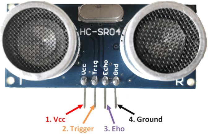
HC-SR04 Hardware Overview
The HC-SR04 ultrasonic distance sensor consists of two ultrasonic transducers: one acts as a transmitter, converting electrical signals into 40 KHz ultrasonic sound pulses, while the other serves as a receiver, listening for the transmitted pulses. When the receiver detects these pulses, it produces an output pulse, the width of which is proportional to the distance from the object in front.
This sensor is excellent for non-contact range detection, offering a range from 2 cm to 400 cm (approximately 13 feet) with an accuracy of 3 mm. It operates at 5 volts, making it compatible with Arduino and other 5V logic microcontrollers.
Technical Specifications
The HC-SR04 sensor comes with the following specifications:
- Operating Voltage: DC 5V
- Operating Current: 15mA
- Operating Frequency: 40KHz
- Maximum Range: 4m
- Minimum Range: 2cm
- Ranging Accuracy: 3mm
- Measuring Angle: 15 degrees
- Trigger Input Signal: 10µS TTL pulse
- Dimensions: 45 x 20 x 15mm
HC-SR04 Ultrasonic Sensor Pinout
The pinout of the HC-SR04 sensor is as follows:
- VCC: Connects to the 5V output from your Arduino to supply power.
- Trig (Trigger) Pin: Used to initiate ultrasonic sound pulses. Setting this pin to HIGH for 10µs triggers the ultrasonic burst.
- Echo Pin: Goes high when the ultrasonic burst is transmitted and remains high until the sensor receives an echo, after which it goes low. Measuring the time the Echo pin stays high allows distance calculation.
- GND: Connects to the ground of the Arduino.
How HC-SR04 Ultrasonic Distance Sensor Works
The sensor’s operation begins when the trigger pin is set HIGH for 10µs. In response, the sensor emits an ultrasonic burst consisting of eight pulses at 40 kHz. This 8-pulse pattern is specially designed to allow the receiver to distinguish the transmitted pulses from ambient ultrasonic noise.
These eight ultrasonic pulses travel through the air away from the transmitter, while the echo pin goes HIGH to initiate the echo-back signal.
If these pulses are not reflected back (indicating no obstruction within the sensor’s range), the echo signal times out and goes low after 38ms (38 milliseconds).
However, if the pulses are reflected back, the echo pin goes low as soon as the signal is received. This generates a pulse on the echo pin, the width of which varies from 150 µs to 25 ms, depending on the time taken to receive the signal.
Calculating Distance
The width of the received pulse is used to calculate the distance from the reflected object. This can be calculated using the simple distance-speed-time equation that you might have learned in high school:
Distance = Speed x Time
Given the value of time (e.g., 500 µs) and knowing the speed (the speed of sound, which is approximately 340 m/s), you can calculate the distance. To calculate the distance correctly, divide the result by two, as the echo pulse indicates the time for the signal to travel to the object and back.
Wiring an HC-SR04 Sensor to an Arduino
Connecting the HC-SR04 sensor to an Arduino is straightforward. Start by placing the sensor on your breadboard. Connect the VCC pin to the 5V pin on the Arduino and the GND pin to the ground pin. Then, connect the Trig and Echo pins to digital pins #9 and #10, respectively. Here are the pin connections:
- VCC: 5V
- Trig (Trigger): Arduino Pin 9
- Echo: Arduino Pin 10
- GND: Ground
Library Installation
To simplify working with the HC-SR04 sensor and measuring distances, it’s advisable to use a library like NewPing. This library can handle tasks like triggering the sensor and measuring the received signal pulse width. It’s quite advanced, supporting up to 15 ultrasonic sensors at once and providing output in centimeters, inches, or time periods. However, this library is not included in the Arduino IDE by default, so you’ll need to install it.
Arduino Example Code
Here’s a basic Arduino sketch that uses the NewPing library to measure and display distances in centimeters on the serial monitor. This sketch is a great way to test the sensor and see distance measurements in real-time.
#include "NewPing.h" // Include NewPing Library

// Hook up HC-SR04 with Trig to Arduino Pin 9, Echo to Arduino pin 10
#define TRIGGER_PIN 9
#define ECHO_PIN 10

// Maximum distance we want to ping for (in centimeters).
#define MAX_DISTANCE 350

// NewPing setup of pins and maximum distance.
NewPing sonar(TRIGGER_PIN, ECHO_PIN, MAX_DISTANCE);

void setup() {
    Serial.begin(9600);
}

void loop() {
    Serial.print("Distance = ");
    Serial.print(sonar.ping_cm());
    Serial.println(" cm");
    delay(1200);
}
After uploading this sketch to your Arduino, open the serial monitor and set the baud rate to 9600 bps. Point the sensor at different objects to observe distance measurements in centimeters.
Understanding the Code
- The sketch begins by including the NewPing library.
- Then, the Arduino pins connected to the TRIG and ECHO pins of the HC-SR04 sensor are defined.
- A NewPing object named sonar is created to manage the sensor and set the maximum distance.
- In the setup section, serial communication is initialized to display the distance measurements.
- The loop function sends a ping and prints the resulting distance in centimeters to the serial monitor. A 500ms delay between measurements provides readability.
Additional Functions in the NewPing Library
The NewPing library offers several other useful functions for working with the HC-SR04 sensor:
- The
ping_in()function provides distance measurements in inches. - You can use duration mode by replacing
sonar.ping_cm()with(sonar.ping() / 2) * 0.0343)to obtain distance in centimeters with decimal precision. - The
ping_median(iterations)method improves accuracy by taking multiple measurements, discarding out-of-range readings, and averaging the remaining ones. You can specify the number of iterations, with the default being 5.
Arduino Project: Contactless Distance Finder
Let’s create a simple project that showcases how the HC-SR04 ultrasonic sensor can be turned into a sophisticated contactless distance finder. In this project, we’ll use a 16×2 Character LCD to display a horizontal bar representing the distance from an object.
Apologies for the previous response. I’ll continue in English.
Wiring
First, let’s connect the HC-SR04 sensor and the 16×2 LCD to the Arduino:
- Connect VCC from the HC-SR04 to the 5V output of the Arduino.
- Link TRIG from the HC-SR04 to digital pin 9 on the Arduino.
- Connect ECHO from the HC-SR04 to digital pin 10 on the Arduino.
- Connect the GND pin from the HC-SR04 to the GND on the Arduino.
For the 16×2 LCD:
- Connect VCC to 5V on the Arduino.
- Connect GND to GND on the Arduino.
- Connect SDA to A4 on the Arduino (if you are using I2C).
- Connect SCL to A5 on the Arduino (if you are using I2C).
Now, let’s create a simple Arduino sketch to read the distance from the HC-SR04 sensor and display it on the LCD.
Arduino Code for Distance Finder
Ensure you have the “LiquidCrystal_I2C” library installed in your Arduino IDE if you are using the I2C interface. If you’re not using an I2C interface, you can use the standard “LiquidCrystal” library. Here’s the code for the distance finder:
#include <Wire.h>
#include <LiquidCrystal_I2C.h> // Use "LiquidCrystal" if not using I2C
#include <NewPing.h>

#define TRIGGER_PIN 9
#define ECHO_PIN 10

LiquidCrystal_I2C lcd(0x27, 16, 2);  // Change 0x27 to your I2C address if different
NewPing sonar(TRIGGER_PIN, ECHO_PIN, 200); // Maximum distance = 200 cm

void setup() {
  lcd.init();                      // Initialize the LCD
  lcd.backlight();                 // Turn on the backlight
  lcd.clear();
  lcd.setCursor(0, 0);
  lcd.print("Distance Finder");
  delay(2000);
}

void loop() {
  delay(100);  // Delay for readability

  // Send a ping and get the result in centimeters
  unsigned int cm = sonar.ping_cm();

  // Display the distance on the LCD
  lcd.clear();
  lcd.setCursor(0, 0);
  lcd.print("Distance (cm):");
  lcd.setCursor(0, 1);

  if (cm == 0) {
    lcd.print("Out of Range");
  } else {
    lcd.print(cm);
    lcd.print(" cm");
  }
}
How the Code Works
- We include the necessary libraries for the I2C LCD and HC-SR04 sensor, create instances for them, and define the trigger and echo pins.
- In the setup function, we initialize the LCD, turn on the backlight, and display a startup message for 2 seconds.
- In the loop function, we use the
sonar.ping_cm()function to send an ultrasonic pulse and get the distance in centimeters. - We clear the LCD, set the cursor to the first line, and display “Distance (cm):”. Then, we set the cursor to the second line.
- We check if the distance reading is zero, which means it’s out of range. If so, we display “Out of Range.” Otherwise, we display the distance in centimeters.
Upload this code to your Arduino, and you should see the distance measurement displayed on the LCD. When an object is within the sensor’s range, the LCD will update with the object’s distance. If there’s no object in range, it will display “Out of Range.”
Certainly, let’s continue in English.
Using HC-SR04 in 3-Wire Mode
The HC-SR04 sensor can also be used in 3-wire mode to save digital I/O pins on your Arduino. In this mode, you use a single I/O pin for both the trigger and echo signals since they are not used simultaneously.
Here’s how to connect the HC-SR04 sensor in 3-wire mode:
- Connect VCC from the HC-SR04 to the 5V output of the Arduino.
- Connect both TRIG and ECHO from the HC-SR04 to digital pin 9 on the Arduino.
- Connect the GND pin from the HC-SR04 to the GND on the Arduino.
This setup allows you to use a single pin for both trigger and echo functions in your code.
Limitations of HC-SR04 Sensor
While the HC-SR04 sensor is quite versatile and useful, it does have some limitations:
- Limited Range: The maximum range of the HC-SR04 sensor is around 13 feet (4 meters). Objects beyond this range may not be detected.
- Angle of Reflection: The sensor relies on sound waves bouncing off objects and returning to the sensor. If an object has a shallow or irregular surface, it may not reflect sound waves effectively, leading to inaccurate measurements.
- Small Objects: Tiny objects may not reflect enough sound waves to be detected by the sensor.
- Sound Absorption: Soft or irregular surfaces, like stuffed animals, can absorb sound waves rather than reflecting them, making it difficult for the HC-SR04 to detect such objects.
- Low Mounting: If the HC-SR04 sensor is mounted close to the ground, it may pick up sound reflections from the floor, which can affect its accuracy.
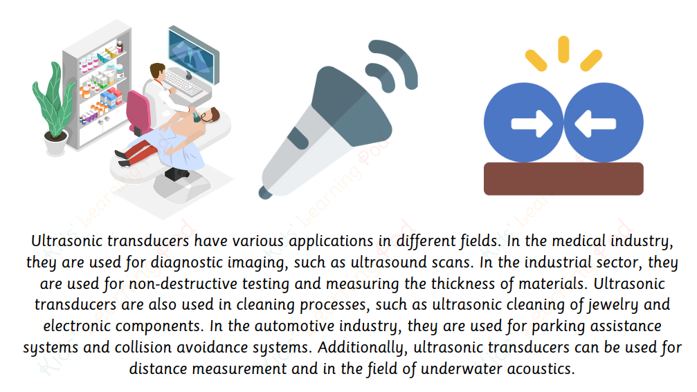
Applications of Ultrasonic Transducers
Ultrasonic transducers, like the HC-SR04, find applications in various fields:
- Factory Automation: They are used in automated factories and process plants to detect the movement of targets, measure distances, and guide web materials. They can provide digital outputs for object detection and analog outputs for distance measurements.
- Automotive: Ultrasonic sensors are commonly found in cars as parking sensors, helping drivers in parking and maneuvering. They are also tested for other automotive applications, including people detection and aiding in autonomous UAV navigation.
- Clear Object Detection: Ultrasonic sensors work well in applications where photoelectric sensors struggle due to the target’s translucence. They are also unaffected by target color or reflectivity.
- Leak Detection: Passive ultrasonic sensors are used to detect high-pressure gas or liquid leaks, or other hazardous conditions that generate ultrasonic sound.
- Ultrasonic Cleaning: High-power ultrasonic emitters are used in ultrasonic cleaning devices. These devices use ultrasonic vibrations to create cavitation in a cleaning solvent, which helps in cleaning objects.
- Ultrasonic Welding: Ultrasonic technology is used in welding and wire bonding, both in plastics and metals, where vibrations created by power ultrasonic transducers are used for joining materials.
- Material Testing: Ultrasonic testing is widely used in metallurgy and engineering to evaluate corrosion, welds, and material defects using different types of scans.